This specification includes the details and procedure of the device functions and how it will benefit within the sports surfacing industry.
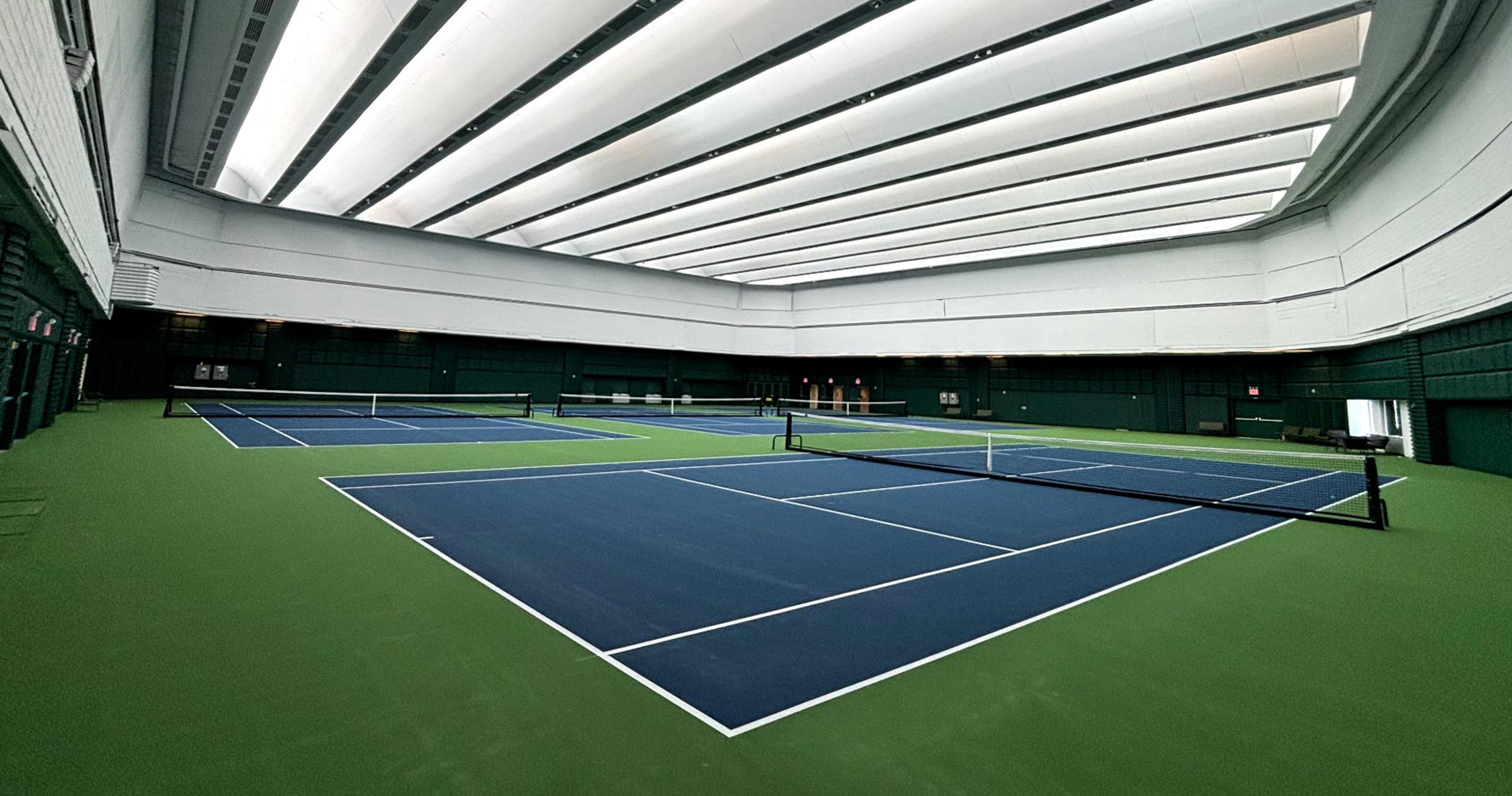
The present invention relates to the resurfacing of cushioned recreational surfaces, particularly tennis courts, and/or track and field surfaces, and/or basketball courts and more particularly relates to a device that is configured for efficient removal of a cushioned recreational surface.
3.1 Many different materials have been used for recreational surfaces in the past, and such use often depends upon the sport for which it is used.
3.2 In 1874, Walter Clopton Wingfield received U.S. Patent No. 157,269 for a “new and Improved Portable Court for Playing the Ancient Game of Tennis”, which resembles the shape of the court used today. However, the shape of the court was modified slightly for Lawn Tennis after Wingfield received his patent, and the sport was adopted by Wimbledon’s All England Croquet Club in 1880.
3.3 Grass was the playing surface of choice for a long period of time. In fact, up until the 1970’s three of our four Grand Slam Tennis tournaments were played on grass, including Wimbledon, the Australian Open and the U.S. Open. The use of Clay (crushed shale, stone, or brick) for tennis courts was predominantly found in Spain and Italy, and remains the surface used in Roland Garros Stadium for the French Open.
3.4 Acrylic tennis court surfaces were not used for tennis tournaments until the 1940’s, but are widely used today, and such cushioned acrylic courts are now used at both the U.S. Open and the Australian Open. These cushioned surfaces are also now commonly used for track and field surfaces, and some outdoor basketball courts.
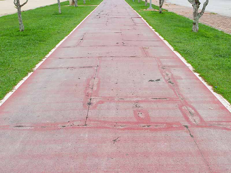
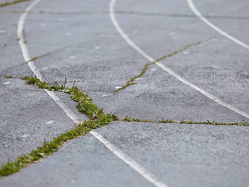
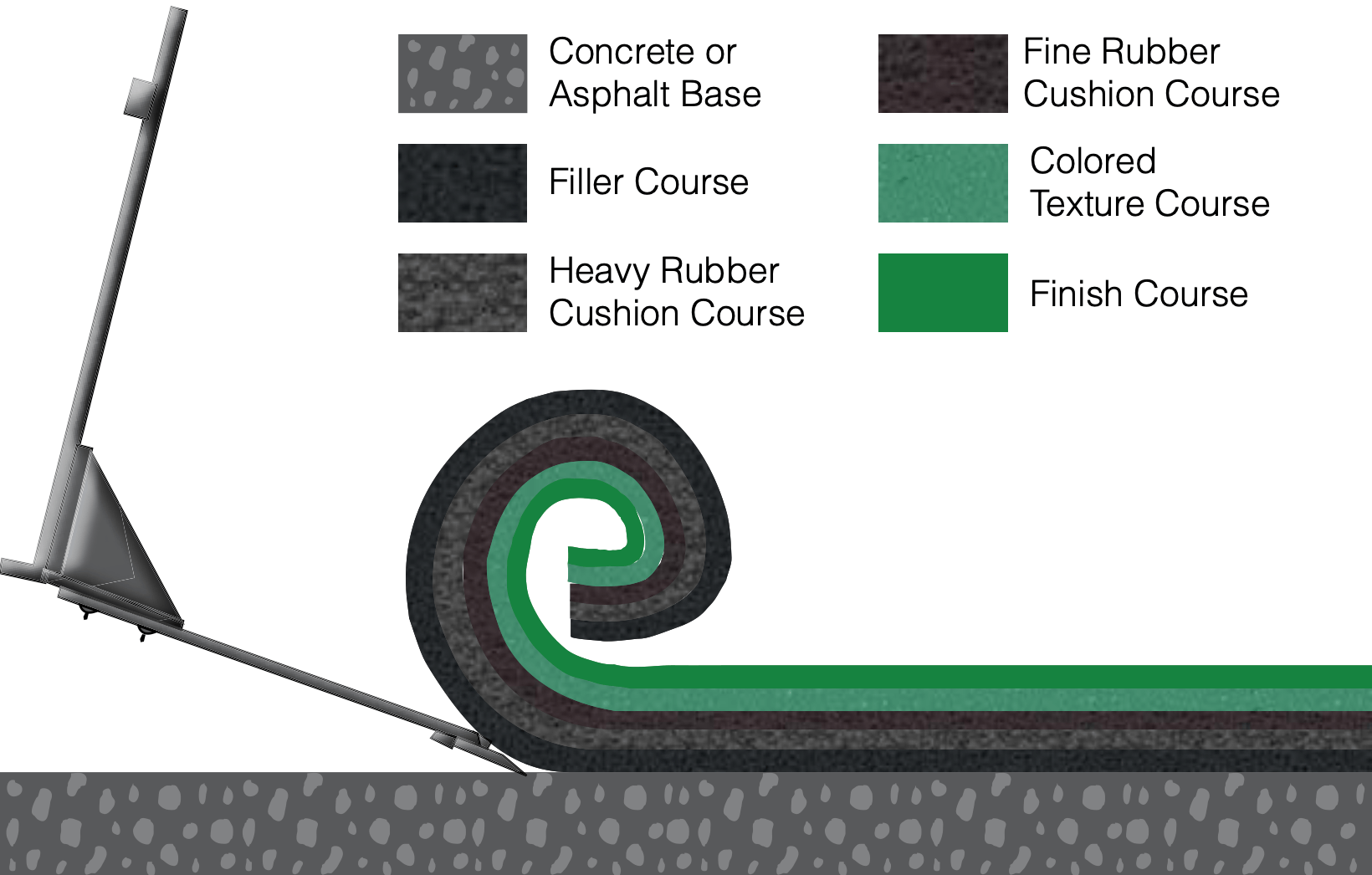
3.5 Today’s acrylic/rubber sport surfaces are formed with a concrete or asphalt base that is covered with one or more layers to seal the base, and to provide some cushioning. These recreational surfaces must be resurfaced periodically—commonly every four to eight years depending on usage and maintenance factors. If the court has not been carefully maintained, moss, mold and fungus may have infiltrated the structure, which may require additional attention (equipment and chemicals for removal). Any cracks that have formed in the concrete or asphalt base would require patching. Also, courts with an asphalt base tend to develop low spots known as bird baths, which also tend to require patching.
3.6 However, these playing surfaces that are used at stadiums that host premier sporting events, such as the U.S. Open Tennis Championship, are desirably resurfaced every year, with additional layers of material placed upon the existing top surface. Periodically, removal of the accumulated multitude of layers must be accomplished with due accuracy not to cause damage to the underlying base, but must also be completed in a timely manner. The present invention is conceived and constructed to improve the effectiveness and efficiency at which the multiple layers of material may be removed.
4.0 Objects of the Invention
4.1 It is an object of the invention to provide a device that may be used efficiently to remove the multiple layers of a recreational surface, particularly a multi-layered tennis court surface.
4.2 It is another object of the invention to provide a device that may be used to efficiently remove the multiple layers of a recreational surface, without damaging its base.
4.3 It is a further object of the invention to provide a device that may be releasably received upon a plurality of different types of transport equipment, which enables the operator to apply a force to the device to move the device to effect removal of the cushioned layers of a recreational surface.
4.4 It is another object of the invention to provide a device that may be constructed to effect rolling of the removed layers of a recreational surface, to create a roll of such layered material, to more easily facilitate its removal from a stadium.
4.5 Further objects and advantages of the invention will become apparent from the following description and claims, and from the accompanying drawings.
5.0 Summary of the Invention
5.1 This summary is provided to introduce a selection of concepts in a simplified form that are further described below in the Detailed Description. This summary is not intended to identify key features or essential features of the claimed subject matter, nor is it intended to be used to limit the scope of the claimed subject matter.
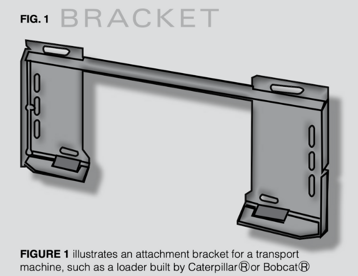
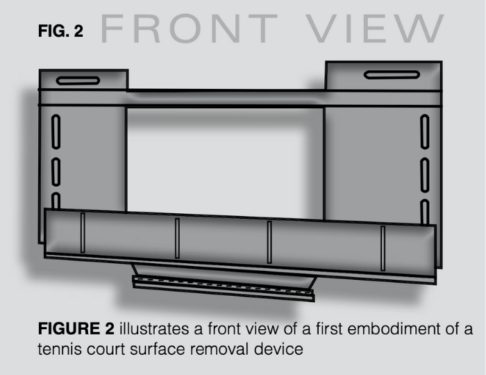
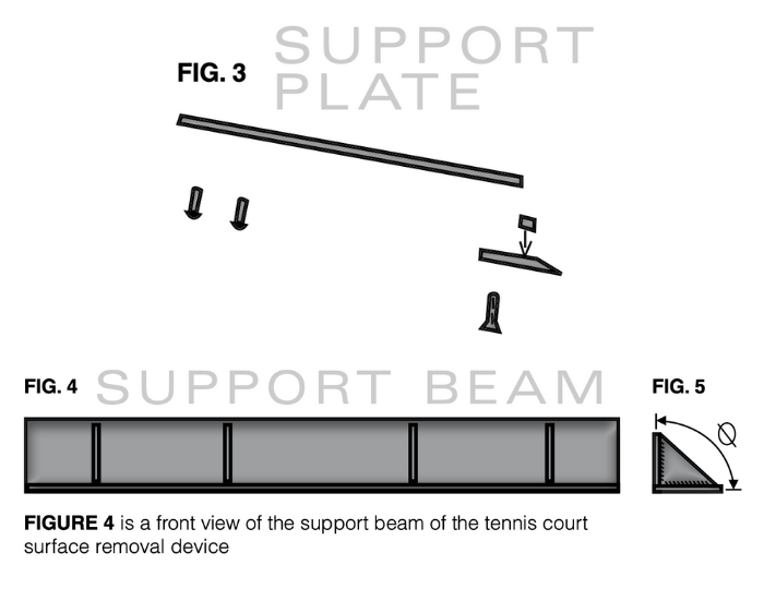
5.2 A machine-mountable tennis court surface removal device may be used in the removal of a plurality of cushioning (and other) layers that overlie a base layer of concrete or asphalt. The removal device may broadly include: an attachment bracket with a first mounting plate and a second mounting plate; a support beam; a support plate; and a scraper. The attachment bracket may be configured to mount the surface removal device to any one of a plurality of different transport machines (e.g., a bobcat, skid-steer, loader etc.). The attachment bracket may be secured to a first portion of the support beam.
5.3 The support plate may be secured to a second portion of the support beam, to be centrally positioned between the first and second mounting plates of the attachment bracket. The support beam may be configured such that the support plate being mounted thereto may extend at an obtuse angle with respect to each of the first and second mounting plates. A top surface of the scraper may be in contact with and mounted to a lower surface of the support plate, and is also desirably centered between the first and second mounting plates of the attachment bracket. The scraper may have a beveled end to form a sharp edge (a tip) that may be used for removal of the plurality of upper layers of the tennis court (or other similar recreational surface) from the base layer of concrete/asphalt.
5.4 For reasons discussed hereinafter, the elongated scraper has a length being between 12 inches and 20 inches, and is preferably between 14 and 18 inches. It has been determined that an optimal length for the elongated scraper is most preferably about 16 inches.
5.5 The configuration of the scraper, which may include an elongated stopper bar fixedly secured to a top surface of the scraper proximate to the beveled edge, may provide the device with the inability to remove the plurality of layers from the base, and to also simultaneously and automatically cause the removed layers to roll up like a carpet runner.